The Hughes & Kettner User Forum

Would you like to react to this message? Create an account in a few clicks or log in to continue.
The Hughes & Kettner User Forum

The Unofficial guitar amp and cabinets forum for users of Hughes and Kettner products. We are not affiliated with Hughes and Kettner!!


2 posters

    BassBase 400 Information

    Phil_T
    Phil_T


    Posts : 17
    Join date : 2017-11-08
    Age : 54
    Location : Under the Sun

    BassBase 400 Information Empty BassBase 400 Information

    Post by Phil_T Mon Nov 26, 2018 5:37 pm

    Hey guys,

    Does anybody know the dimensions of a BassBase 400?
    Just picked one up online for a steal and I'm attempting to have a rack case custom built for it, and there's practically no information of this product online.

    Thanks in advance!


    Last edited by Phil_T on Mon Dec 10, 2018 12:17 pm; edited 1 time in total
    bordonbert
    bordonbert


    Posts : 1772
    Join date : 2015-01-28
    Age : 72
    Location : Southern England

    BassBase 400 Information Empty Re: BassBase 400 Information

    Post by bordonbert Tue Nov 27, 2018 3:47 am

    I've got no experience of that myself Phil but the manual available online which you must have seen says it is:  LxHxD;  605mm x 713mm x 460mm  for the combo;  19” x 2HU for the head.

    I would guess you have the head as you want a rack for it so the 2HU would be 3.5" or 89mm in height.  From pics it looks to be a touch less than the width of the unit and that should be close enough for your rack as they will go in fixed steps of depth I would guess.  You should be able to guage the depth from this:  Racked BassBase 600  I know that's the 600 but usually the depth will be the same. If you want more accurate sizing then I would ask on the Hughes & Kettner Facebook page where someone usually gets back to you fairly quickly.  That's much faster than emailing them which gets lost.


    _________________
    Newcastle Brown, can sure smack you down
    You take a greasy wh*re, and a rollin' dance floor
    You know you're jailhouse bound!

    Rock On Humble Pie
    Phil_T
    Phil_T


    Posts : 17
    Join date : 2017-11-08
    Age : 54
    Location : Under the Sun

    BassBase 400 Information Empty Re: BassBase 400 Information

    Post by Phil_T Mon Dec 10, 2018 12:23 pm

    Thanks for the info and the swift reply, bordonbert, I really do appreciate it.
    I've tried both the H&K Support page [I emailed them profusely, quite a number of years ago, as well as recently -- never received a response from them.
    I've also tried the FB page -- and I received a response stating they will contact H&K and provide me with updates.
    Phil_T
    Phil_T


    Posts : 17
    Join date : 2017-11-08
    Age : 54
    Location : Under the Sun

    BassBase 400 Information Empty Re: BassBase 400 Information

    Post by Phil_T Mon Dec 10, 2018 12:32 pm

    Hey bordonbert, perhaps you can assist me with a technical query...
    I recently purchased a Bass Base 400 head, in which all the  [or remaining] xenon bulbs were fried. The BB600 Service doc. states that these bulbs are T10, 5w/12v wedge base xenon light bulbs.

    To your knowledge, do you know if one can perform an LED mod to the control panel, as opposed to using these old-fashioned bulbs?
    Meaning: can the T10 xenon bulbs be swapped with T10 LED replacements?

    Thanks in advance!
    bordonbert
    bordonbert


    Posts : 1772
    Join date : 2015-01-28
    Age : 72
    Location : Southern England

    BassBase 400 Information Empty Re: BassBase 400 Information

    Post by bordonbert Tue Dec 11, 2018 7:54 am

    Hi Phil.  I know from recent experience that you absolutely can!  These are the same bulbs that are used in the computer dashboard of my car, (it's quite an old European model and the screen is an orange LED backlit one).  I've just replaced my original bulbs with T10 LED versions and it was a straight plugin with the new ones.  There are a couple of points worth pointing out in using LEDs in general, (as always Wink ).

    LEDs MUST have a series current limiting resistor in series with them.  Sometimes this is built into your circuit and it is a plain LED you are plugging in, at other times the LED must carry that in its own package when it is usually described as an 'LED Indicator'.  As you do not have this built into your existing bulb circuitry, just make sure to get replacements with the resistor already fitted in the LED unit.  The car T10 12V units are correct for this.  I keep plugging this point to people so apologies if I am preaching again but, as always, others coming across it may benefit.  An LED is NOT the same as a bulb in any way other than it gives out light.  The bulb is basically pretty much a resistor designed to get very hot which needs to see a particular voltage to dissipate the correct designed amount of heat.  With its fixed (more or less) resistance and a reasonably steady supply voltage it will then set its own current and settle at the correct working point.  It remains there pretty much stable with only sensible changes in current for sensible changes in voltage meaning nothing necessarily disastrous occurs in normal use.  An LED is not that way inclined.  LEDs need to have their current set by other external components and they will set themselves at their working voltage from that point on.  They can technically do this the other way around in the same way as a bulb except for one practical reason, the amount the current increases as the supplied voltage increases.

    The way the voltage and current are related in the two devices is different.  In the bulb it is fairly much straight line linear and that means double the voltage and you basically double the current, so it is practical to control the light output by setting that voltage as the current does not change by extremes.  In the LED the relationship is very skewed.  If you consider starting with 0V across the LED terminals and increasing the voltage very slowly you first get nothing, no current flows.  At not much over 1V most red LEDs will start to glow dimly and a very tiny current will flow.  With a small increase in voltage to around 1.3-1.8V depending on the type, the LED is fully lit and the current has increased to its working level, usually around 10-20mA.  Finally, with only a very small increase from there of a small fraction of a volt, the current increases drastically, usually enough to damage the LED.  The levels vary greatly between LED types and colours but the principle is always the same.  An LED cannot be controlled practically by feeding it a set voltage, when it reaches its working point only a tiny increase in that voltage will cause massive current increase and blow it.

    So how do we use it?  We feed it a much higher voltage than it alone requires and soak up the excess across a resistor.  The resistor then defines what the current will be through it, (Ohm's Law V=IxR and all that), and as it is in series with the LED that must pass the same current.  So the resistor value can be chosen to set the current to what the LED needs to see.  In this way the resistor more or less takes over and reduces that steep change dramatically to bring the LED's massive current increase back under control.  That's why it is called a 'current limiting resistor'.

    You already have circuitry set up for a 12V car bulb, so you only need to make sure that the LEDs have a resistor in the unit and that is calculated to be optimum for a 12V supply.  12V T10 car replacements will be fine.

    The other fact about LEDs is that, unlike bulbs which are just resistors, they are diodes.  This means that they will only pass current in one direction.  You have to plug them in the right way round or you get no light out.  Fortunately, the ones I got were not marked in any way but simply gave no output when they were incorrectly fitted and I just had to unplug them and turn them round to get them to work.  I think most automotive types are like that.

    So to round off the LED info, unlike most other diodes LEDs do not stand particularly high voltages in reverse.  Usually around 5V is the quoted maximum and the lowest normal diodes are usually specd at 50V.  With a resistor in series this is much more forgiving though some LEDs may actually give light output when they have exceeded their own particular safe reverse voltage level. This is by a different principle than the one they are designed to work under with a normal forward voltage and it is not a long term safe way of using them.  Make sure you get yours in the correct orientation.


    _________________
    Newcastle Brown, can sure smack you down
    You take a greasy wh*re, and a rollin' dance floor
    You know you're jailhouse bound!

    Rock On Humble Pie
    Phil_T
    Phil_T


    Posts : 17
    Join date : 2017-11-08
    Age : 54
    Location : Under the Sun

    BassBase 400 Information Empty Re: BassBase 400 Information

    Post by Phil_T Tue Dec 11, 2018 11:47 am

    Extremely helpful information! I'll do a little more research to see if I can find me a few Plug-and-Play LED's...

    Thanks again bordonbert!
    Phil_T
    Phil_T


    Posts : 17
    Join date : 2017-11-08
    Age : 54
    Location : Under the Sun

    BassBase 400 Information Empty Re: BassBase 400 Information

    Post by Phil_T Fri Jan 04, 2019 3:24 pm

    LED 'Mod" seems to be working fine! Once again, thanks for the extremely helpful tips bordonbert!
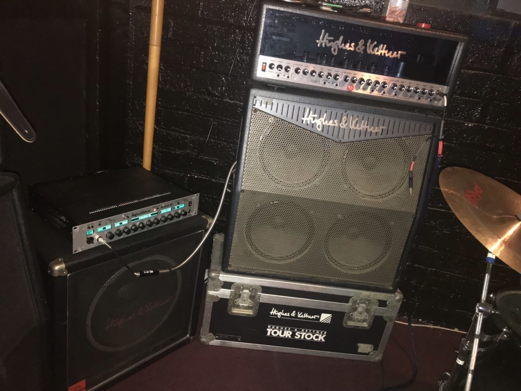
    BassBase 400 Information 2hks10
    bordonbert
    bordonbert


    Posts : 1772
    Join date : 2015-01-28
    Age : 72
    Location : Southern England

    BassBase 400 Information Empty Re: BassBase 400 Information

    Post by bordonbert Fri Jan 04, 2019 7:15 pm

    Hey hey, lookin' good there! Glad it worked out.

    It's a very small victory in the name of technology that we can go forwards with such a simple but profound upgrade. The LED bulb is so much better in almost every way. Now if only people would listen re other modern component types and PCBs and the other Luddite bits of hang on from the 60s, we could all be working with much better amps! Laughing Mind you, we mustn't underestimate the subtle effect that LEDs have on the sound of our kit. This genuinely was a hot topic in hifi for a while, the "sound" of LED indicators. Best do some serious listening tests until you can convince yourself you can hear the obvious degradation of sound now you've changed from early '90s bulbs to a more modern type.

    Well done for getting stuck in there and sorting it and many thanks for getting back to update us. Happy pluckin' Phil!


    _________________
    Newcastle Brown, can sure smack you down
    You take a greasy wh*re, and a rollin' dance floor
    You know you're jailhouse bound!

    Rock On Humble Pie

    Sponsored content


    BassBase 400 Information Empty Re: BassBase 400 Information

    Post by Sponsored content


      Current date/time is Fri Mar 29, 2024 2:07 am