The Hughes & Kettner User Forum

Would you like to react to this message? Create an account in a few clicks or log in to continue.
The Hughes & Kettner User Forum

The Unofficial guitar amp and cabinets forum for users of Hughes and Kettner products. We are not affiliated with Hughes and Kettner!!


5 posters

    TU 18 Footswitch

    Eighthnote
    Eighthnote


    Posts : 5
    Join date : 2015-10-10

    TU 18 Footswitch Empty TU 18 Footswitch

    Post by Eighthnote Tue Oct 13, 2015 9:25 pm

    Hello all.............new to this forum. I own a Tubemeister 18 and need to be able to use the foot switch. Not much luck so far. I'm going to post two pics here. One is of a std. 2 button (stereo plug with LED) foot switch. The next pic is the schematic of the same switch. I know why a Am7 and a Cmaj6 is the same but I don't know why this F&*^%$#$ pedal doesn't work. If someone with the electronic thing going on can explain it to me I would very much appreciate it.
    Let be clarify what I mean by the foot switch doesn't work. It works, the LEDs on the pedal light up and turn off. However as soon as I plug into the head it activates the lead channel. When I press the right foot button the clean channel (yellow light) comes on but the lead channel light stays on. The amp does not go to the clean only channel. I would think that when I plug this foot pedal in nothing would happen until I press one of the buttons. No clean channel with the foot switch is possible even though the yellow clean light is lit. HELP............Thanks......... bounce

    TU 18 Footswitch <a href=TU 18 Footswitch P-h471-led_functional_diagram" />

    TU 18 Footswitch <a href=TU 18 Footswitch Pedal" />
    bordonbert
    bordonbert


    Posts : 1790
    Join date : 2015-01-28
    Age : 72
    Location : Southern England

    TU 18 Footswitch Empty Re: TU 18 Footswitch

    Post by bordonbert Wed Oct 14, 2015 7:49 am

    For that switch to work it depends on the way the unit responds to the signal levels. You have a situation where the control signals on the tip and ring are being fed from an output impedance. You have switches which short it down to ground on the sleeve or leave it open. But when they leave it open there is a LED and 1k resistor across it. If that is a low enough impedance the amp may still detect it as a short in relation to its own impedance! So you would have both signals shorted in any switch position.

    Are you able to temporarily disconnect the LEDs to try it with just the switches?

    I remember posting something about the signal logic and levels in a previous thread. I'll have a look when I get a minute and get back to you.


    _________________
    Newcastle Brown, can sure smack you down
    You take a greasy wh*re, and a rollin' dance floor
    You know you're jailhouse bound!

    Rock On Humble Pie
    bordonbert
    bordonbert


    Posts : 1790
    Join date : 2015-01-28
    Age : 72
    Location : Southern England

    TU 18 Footswitch Empty Re: TU 18 Footswitch

    Post by bordonbert Wed Oct 14, 2015 7:58 am

    Have a look at this thread when you can.  There is info in there which might help.  We can go forward from there.

    Control Voltages
    Eighthnote
    Eighthnote


    Posts : 5
    Join date : 2015-10-10

    TU 18 Footswitch Empty Rats

    Post by Eighthnote Wed Oct 14, 2015 1:53 pm

    bordonbert wrote:Have a look at this thread when you can.  There is info in there which might help.  We can go forward from there.

    Control Voltages

    Well, that's slightly over my comfort level without some help. Having to disconnect the LED's is disappointing but it is what it is. I'm posting a pic of the wiring inside. If you could step me through what I need to do I do have some soldering ability. I just do not have the electronic background. If you could give me an option for leaving the LED's working that would be great. If it's just a matter of taking the resistor and LED's out of the loop then it is what it is. Thanks for the guidance.

    TU 18 Footswitch <a href=TU 18 Footswitch PedalSch" />
    bordonbert
    bordonbert


    Posts : 1790
    Join date : 2015-01-28
    Age : 72
    Location : Southern England

    TU 18 Footswitch Empty Re: TU 18 Footswitch

    Post by bordonbert Wed Oct 14, 2015 6:43 pm

    No, you misunderstood what I meant.  I was saying just disconnect them temporarily to prove it is the LED current which is the problem.  Once you have disconnected them, (at one end only and it looks as though breaking where the resistor and LED join may be the easiest spot), you will be able to see whether the switches then work without them attached.  That way we have proved that it is the LED current draw which is false triggering the system.

    If that proves to be the case then we can try to simply increase the resistor value to a point where it does not cause the problem.  I would guess about 10k though you may get away with less.  Unfortunately that will probably mean a noticeable decrease in the light output of the LEDs.  You may be able to get away with a not very high resistance and still maintain a sensible light output.

    Did you catch the part where I mentioned that with the type of switch setup you have you cannot get the LEDs to function like the ones on the amp.  If you can get these to work you will have the following indications.

    LED1: Clean / Drive
    LED2: Crunch / Lead

    Clean: LED1 ON / LED2 ON or OFF (as currently selected by switch 2)
    Crunch: LED1 OFF / LED2 ON
    Lead: LED1 OFF / LED2 OFF

    Without powering the unit and adding a LED control circuit block you can't do better than that I'm afraid.

    EDIT:  Wait a minute, you may be able to do better.  If we find we can make the LED work without triggering the control switching we can add a second LED for the Crunch/Lead selection.  Then we can set one side of the Crunch/Lead switch to work with one LED and a high resistor value without shorting, and the other to work as it is now with a low value resistor to short.  That way you have an LED for every selection.  The resistor values are the key thing there.  LEDs will not necessarily be balanced in light output though and you still haven't solved the problem of the Crunch/Lead selection LED being on when you are on the Clean channel.

    EDIT EDIT: Just had a brainwave.  Yes you can solve the problem of the Crunch/Lead LEDs lighting up when Clean is selected.  The switches are DPDT types and have a whole spare section which is just currently paralleled up.  We can use that to short down the Crunch/Lead signal from the jack ring while the Clean is selected on the Clean/Drive switch.  That way the Drive side LEDs are extinguished until Clean is deselected then the short is removed and their own switch controls their action.

    This depends on you finding out about your switch working without the LED attached.  Be careful when you disconnect the LED.  Make sure to have the heat applied for only a couple of seconds otherwise you will burn out the LED.
    Eighthnote
    Eighthnote


    Posts : 5
    Join date : 2015-10-10

    TU 18 Footswitch Empty Re: TU 18 Footswitch

    Post by Eighthnote Sun Oct 18, 2015 5:34 pm

    Hello, thanks again. Here's where we're at with getting the FS to behave. I took my soldering iron and simply heated the joint where the 1K resistor was soldered to the lead off the switch. Both switches of course. Pedal works exactly like it should. No LED's but the lights on the amp head and my ears can tell me everything I need to know. Next I will track down some higher value resistors starting at 10K and if I understand your electronic lesson correctly I can re-introduce a resistor into the circuit. Am I on the right track here? Thanks again.
    bordonbert
    bordonbert


    Posts : 1790
    Join date : 2015-01-28
    Age : 72
    Location : Southern England

    TU 18 Footswitch Empty Re: TU 18 Footswitch

    Post by bordonbert Mon Oct 19, 2015 2:27 am

    Haha! I love it when a plan comes together! Well done Eighthnote, exactly what was needed. You have proved that the problem is the LED and resistor drawing current and the TM interpreting that as a short and a sign that it needs to switch. What we now need to do is to get a higher resistor in there and reduce that current until it doesn't see it as a short. We can then see if the LED will still give enough light at that current to be useful. If you can hold off for a couple of days I will dig out my own TM and check it out here as I have a full range of resistors to test with and can then tell you what works.

    Incidentally, as well as the LEDs, be very careful with the amount of heat you put into those switches. I have worked with that type and can tell you they are soft and delicate! The whole unit softens and distorts very quickly and the terminals move around making them unserviceable with just a little too much heat.

    Just as a final observation for now, it ALWAYS pays to take a logical engineering approach with guitar kit. It is just another arm of engineering and the whole concept of "mojo" is simply "engineering that we haven't explained yet". Except that most of it HAS been explained but the die hard mojoists don't understand it and insist that things are down to "just knowing". If you train yourself to look at every problem with an engineer's eye along with your musician's ear you will not only fix it faster and more reliably and often cheaper, you'll also understand it and be able to fix more complicated issues in the future. You get better and more able that way, not just appear to be cleverer.

    I'll get back to you with some findings when I've had a chance to try it out.
    Eighthnote
    Eighthnote


    Posts : 5
    Join date : 2015-10-10

    TU 18 Footswitch Empty Re: TU 18 Footswitch

    Post by Eighthnote Mon Oct 19, 2015 2:46 am

    Perfect. I look forward to what you find. FYI.......I really didn't have to apply heat directly to the switches. Whoever designed these things actually soldered a separate short wire from the switch terminal so the resistor is actually soldered to this short wire. Looking at the wire into the LED's off the resistor though looks problematic. That wire appears to go right into the small LED's without any real access to where they connect. One thought is to simply cut those wires near the LED's and use them to solder the new resistor into the circuit. Just like the short wires near the switch. Right now I'm just happy the switch works and my amp head responds as it should. Cheers..............
    bordonbert
    bordonbert


    Posts : 1790
    Join date : 2015-01-28
    Age : 72
    Location : Southern England

    TU 18 Footswitch Empty Re: TU 18 Footswitch

    Post by bordonbert Tue Oct 20, 2015 11:13 am

    I've talked to H&K service team about this and they are more confused than we are. geek They are trying to convince me that we need a smaller resistor rather than a larger. That doesn't work either in theory or in practice! I've tested this here on my own TM36 and in fact I get perfect functioning with a LED + 1k resistor, yours must be a tad more sensitive than mine or the LED choice makes a difference. Either way you can't be far out with that 1k.

    I have perfect working with a 1k5 resistor, though the LED is a little duller. I would start there. As resistors are so cheap try to get 1k5, 1k8, 2k2, 2k7 and select the lowest value which works for you out of them. You could test just the resistors manually by holding one without the LED across the stereo jack plug tip to sleeve until you select one where the channel doesn't change. The addition of the LED would then give you a little safety margin.

    So you don't need to go to a really high value to sort this out at all, just a slight increase from your 1k should work.
    Eighthnote
    Eighthnote


    Posts : 5
    Join date : 2015-10-10

    TU 18 Footswitch Empty Re: TU 18 Footswitch

    Post by Eighthnote Tue Oct 20, 2015 11:59 am

    Thanks for the info. I had you until you wrote " You could test just the resistors manually by holding one without the LED across the stereo jack plug tip to sleeve until you select one where the channel doesn't change." ....... I've got the "across the stereo jack plug tip to sleeve" but I'm missing something. The stereo jack plug would be inserted into the foot switch jack. I do not understand how I could place a resistor tip to sleeve while the stereo jack is in the socket. I could do that inside the switch box by removing the 1K and manually hold higher values incrementally where the 1K was located. Straighten me out here.........what am I missing? Thank you again for your help.
    Another variable I see when buying resistors that there a 1k8 1watt and 1k8 2watt. Can you enlighten me on why or why not I should use one or the other? Again thank you.........
    bordonbert
    bordonbert


    Posts : 1790
    Join date : 2015-01-28
    Age : 72
    Location : Southern England

    TU 18 Footswitch Empty Re: TU 18 Footswitch

    Post by bordonbert Wed Oct 21, 2015 3:51 am

    Sorry, I should have explained a bit more. I use two double footswitches on my pedal board and I've put my footswitches on it with my other pedals. I fitted a small sheet aluminium panel at the back to carry two jack sockets. I cut the switch leads short and fitted the two jack sockets in p[lace of the plugs and mounted them on the panel so the switches are now an integral part of the board. I then just set up the board with the usual connections plus two stereo jack leads to the amp carrying the switching, one to the channel switches and the other to the effects/loop switches. It just makes the whole thing more portable.

    I meant that with the stereo jack inserted in the amp you can work on the other bare end. For the test you can use either use a stereo jack lead if you have one or just a plain old mono guitar lead. Just insert the jack lead into the channel switch socket on the amp. If it is a normal mono plug, the Crunch/Lead switch on the ring will be permanently shorted out selecting Lead but that isn't a problem at the moment as the Clean/Drive switch will still work perfectly on the tip. Do your testing across the tip and sleeve of the bare plug at the outer end of the lead.

    The resistor you want is the smallest you can handle. There is absolutely no power worth worrying about being dissipated in these resistors so 1W or 2W would be wildly oversized for your needs. 1/8W or 1/4W will be perfect.
    bordonbert
    bordonbert


    Posts : 1790
    Join date : 2015-01-28
    Age : 72
    Location : Southern England

    TU 18 Footswitch Empty Re: TU 18 Footswitch

    Post by bordonbert Wed Oct 21, 2015 9:38 am

    And the penny has dropped and I have the answer to this puzzle!

    From a user review of their FS-2 footswitch I found that H&K use the following indications:  Clean = No LEDs;  Crunch = 1 LED;  Lead = 2 LEDs.  Now that is different to what your footswitch would produce.  And the answer is because H&K wire up their LEDs differently.  They don't put them across the switch, they put them in series with it.  To set it up like H&K you need to change your setup to be something like this:

    TU 18 Footswitch <a href=TU 18 Footswitch Revise10" />

    That shouldn't take too much doing.  The 1k resistors are totally optional!  The circuit will work without them being there at all with a higher light output.  If you want to remove them just bridge across them in the schematic.  You will need to try it to see what the LED light level turns out like.  I would wire them up with the 1k in there and just short across it with a short piece of wire to see the difference.  If you prefer it just solder the wire across.  That way you have a handy dimmer switch if it gets irritating by just removing it again.  Be careful with overheating the LEDs and switches as I mentioned before.

    Now this will mean that your LED indications change!  You now get the following logic: Clean: No LEDs;  Crunch: 1 LED;  Lead: 2 LEDs.  If you think about it that's logical.  Increased drive means more LEDs come on.  Or you could replace the Reds with any other colour you want and have a Yellow for Crunch and a Red for Lead to kind of match the panel lights.

    (Or you could go the whole hog and do what I did, build a little driver and logic circuit and power it from my pedal board supply and have them exactly the same as the panel lights, one on at a time for each channel and Blue, Yellow and Red. cheers )
    ckhorvo
    ckhorvo


    Posts : 3
    Join date : 2018-03-28

    TU 18 Footswitch Empty Same problem, help!

    Post by ckhorvo Wed Mar 28, 2018 9:40 am

    hello! Well i know this is an old thread but it has been difficult to find info and when I searched in other forums almost all the pictures' links were broken. I hope you can help me.

    I have the same problem with my footswitch as Eighthnote, I read all but I get lost in the last post. So Bordonbert do you find a total different answer to the problem where you say "To set it up like H&K you need to change your setup to be something like this" I just have to try to follow the schematic you posted? no change in resistor values? Should I just put them in series with the connector? It is important to mention that where I live it's impossible to buy the original FS and very expensive to buy abroad. Well, i hope you guys are still in here X) Thanks in Advance!
    bordonbert
    bordonbert


    Posts : 1790
    Join date : 2015-01-28
    Age : 72
    Location : Southern England

    TU 18 Footswitch Empty Re: TU 18 Footswitch

    Post by bordonbert Fri Mar 30, 2018 8:08 am

    Hi Ckhorvo. Glad this old thread helped you. It shows that, just as we have always said, a fuller answer than the original poster needed may help others who come along with the same or closely related questions. Since I posted this info I have had a look at the situation again and can add a couple of minor things I don't think were mentioned in the original posts.

    When you insert the footswitch the amp front panel Channel and Boost switches are removed from circuit. They will do nothing when pressed. However, their LEDs will continue to display your selection to match the footswitch LEDs automatically. When you remove the footswitch jack the system reverts back to the settings of those front panel switches even if that is different to the selections of the footswitch. This is not a system where the selections are digitally stored in the amp in any way, it is purely physical.

    Having now looked into the circuitry which drives the selection and display process I can tell you that the 1k resistors in my own schematic are redundant! You don't need them at all. The internal amp circuitry has its own current limiting and all we are doing is adding another LED in series with the internal one.

    Can I first make sure which amp model you have? This is relevant because the TM18/36 have different numbers of channels and hence will work differently.


    _________________
    Newcastle Brown, can sure smack you down
    You take a greasy wh*re, and a rollin' dance floor
    You know you're jailhouse bound!

    Rock On Humble Pie
    bordonbert
    bordonbert


    Posts : 1790
    Join date : 2015-01-28
    Age : 72
    Location : Southern England

    TU 18 Footswitch Empty Re: TU 18 Footswitch

    Post by bordonbert Fri Mar 30, 2018 8:15 am

    Incidentally, I don't know if you found this thread but, if yours is a TM36, it is possible to make the footswitch LEDs follow the front panel LEDs. It does require making up a small control circuit on perf board with a few transistors on it which many people will not be able to do but it means you can have a "Blue/Yellow/Red" setup instead of a "This one/That one/Both" type of display on your pedal.

    More accurate channel display for TM36 LEDs


    _________________
    Newcastle Brown, can sure smack you down
    You take a greasy wh*re, and a rollin' dance floor
    You know you're jailhouse bound!

    Rock On Humble Pie
    ckhorvo
    ckhorvo


    Posts : 3
    Join date : 2018-03-28

    TU 18 Footswitch Empty Re: TU 18 Footswitch

    Post by ckhorvo Sun Apr 15, 2018 7:12 pm

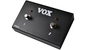
    I'm sorry for taking so long time to reply. So this is the switch i have, a Vox VFS2A that i want to use in a tubemeister 18. As I mentioned before, when pressed it changes only one time from clean to lead and then it stays that way. So this is the wiring, resistors are 1.5k. I hope you can help me to make it work! Thanks in advance Very HappyTU 18 Footswitch Descar10
    TU 18 Footswitch Img_2011
    TU 18 Footswitch Img_2010
    bordonbert
    bordonbert


    Posts : 1790
    Join date : 2015-01-28
    Age : 72
    Location : Southern England

    TU 18 Footswitch Empty Re: TU 18 Footswitch

    Post by bordonbert Mon Apr 16, 2018 5:48 am

    Great clear shots of the insides of the footswitch ckhorvo, that makes things much easier.  And you have confirmed it as a TM18 which has only two channels so it's pretty easy.

    Since that original posting which you found I have seen the full amp schematics and can see exactly what the H&K guys were talking about.  (They work with the current not a voltage!)  To make it work exactly like the H&K ones follow these steps in absolute order.  I have added some extra ones so you can't get confused with things like the LED orientation which is important or between the two switch functions.

    1 )Disconnect the Red wire and LED at the switchTake care with heating, work quickly for only a short time, these switches are VERY easy to overheat and melt
    2 )Reconnect just the Red wire and the LED legThis will make sure to keep the LED the same way round as it originally was
    3 )Remove the resistor from the LED and switch leaving the black wire connected to the switchYes completely as it is not needed at all
    4 )Solder the LED leg to the switch middle terminal with a short wireThat's the end you have just taken the resistor off to the terminal you took the Red wire off
    5 )Have a coffee!The LED is now in series with the lead to the switch and the same way around as it originally was
    6 )Disconnect the White wire and LED at the switchAgain, take care with heating as those switches are really soft
    7 )Reconnect just the White wire and the LED legThe LED is the same orientation as before
    8 )Remove the resistor from the LED and switch leaving the black wire connected to the switchSame as before, it is not needed at all
    9 )Solder the LED leg to the switch middle terminal with a short wireAgain, that's the end you have just taken the resistor off
    10 ) Plug it in and test itYou should have both switches in series with their LED

    I have also attached a schematic of what you are trying to produce and a quick rough pic of how it should turn out which might make things clearer.
    Attachments
    TU 18 Footswitch Attachmentfootswitch_wiring.jpg
    You don't have permission to download attachments.
    (24 Kb) Downloaded 34 times
    TU 18 Footswitch AttachmentSwitch_Wiring.jpg
    You don't have permission to download attachments.
    (22 Kb) Downloaded 23 times


    _________________
    Newcastle Brown, can sure smack you down
    You take a greasy wh*re, and a rollin' dance floor
    You know you're jailhouse bound!

    Rock On Humble Pie

    radiobends likes this post

    ckhorvo
    ckhorvo


    Posts : 3
    Join date : 2018-03-28

    TU 18 Footswitch Empty Re: TU 18 Footswitch

    Post by ckhorvo Fri Dec 07, 2018 2:40 pm

    hey! I never said thankyou!!! Very Happy. I went through all the steps you mentioned and It worked Very Happy!!! now I can use the switch! Thanks again! Greetings from Chile What a Face
    bordonbert
    bordonbert


    Posts : 1790
    Join date : 2015-01-28
    Age : 72
    Location : Southern England

    TU 18 Footswitch Empty Re: TU 18 Footswitch

    Post by bordonbert Sat Dec 08, 2018 9:44 am

    You're very welcome Ckhorvo. Very Happy It's really nice to hear from people as to how the fixes and mods work out for them. Not everyone bothers to post afterwards I'm afraid and you're left not knowing whether the advice you gave was correct in their case.

    Everything we post here helps more players than just the handful who check it out as active forum members. There are many people who will find the info useful who just come across it in Google searches for a particular problem. That's why I still insist on writing those long replies with as much info as I can cram in rather than just a two line "do this, then this, there it's fixed" response. I may not be around to explain at some future date and I'd still like to think I can make what I know available.

    Anyway, thanks for the update and I'm glad to hear it is still working as it should. Es bueno ver que la guitarra aún se disfruta en Chile! cheers


    _________________
    Newcastle Brown, can sure smack you down
    You take a greasy wh*re, and a rollin' dance floor
    You know you're jailhouse bound!

    Rock On Humble Pie
    rumworks
    rumworks


    Posts : 22
    Join date : 2020-04-27

    TU 18 Footswitch Empty Re: TU 18 Footswitch

    Post by rumworks Mon Apr 27, 2020 11:24 pm

    Howdy all. This seems to be the place that may have an answer for me. I’ve got a h and k Tubemeister 18 myself and I’m pretty happy with it. Recently, I purchased a Carl Martin MK3 Octa-Switch. It has two external switches for controlling channels on your amp or amps depending on what you want to do. I have been using the H & K FS-2 footswitch but now, would like to be able to use the switching ability on the Carl Martin instead of the FS-2 so everything is right there on one board. The Carl Martin just needs one 1/4 inch jack input for each channel to be controlled. In other words, I need the cable from the FS-2 and the end where the pedal is now is what I need to wire into two separate 1/4 inch jacks. Personally though, I’d like to keep the FS-2 intact and just have a cable that has one stereo plug and two mono plugs. I think this would work. Is it as simple as that? I see the wiring chart above. Is that the same chart as my FS-2 footswitch? I sure would like to get this going. Any help would be greatly appreciated!

    Rick


    Last edited by rumworks on Tue Jul 12, 2022 2:53 pm; edited 2 times in total (Reason for editing : Wrong model number)
    bordonbert
    bordonbert


    Posts : 1790
    Join date : 2015-01-28
    Age : 72
    Location : Southern England

    TU 18 Footswitch Empty Re: TU 18 Footswitch

    Post by bordonbert Tue Apr 28, 2020 10:40 am

    Hi Rumworks.  I know you have read a fair bit on this above but I'll not assume you have any details yet in the interest of clarity.  It should be easier to get it right first time that way.  It will make for a long post but one which should give you all you need to get going without too much back and forward for more info.  Incidentally, if anyone else reads this and understands the process, your opinion of whether I'm reading this correctly or not would be appreciated.  The processes are very simple but I'm not an Octa Switch user nor do I use any switcher unit as I only use a few pedals and they are usually set at the start of a number and then rely on only switching a single pedal if at all.

    If I have the Octa Switch action correct then my guess would be that you can do this and all you need is a Y-Splitter setup, a couple of cables and a couple of blank 1/4" plugs.  It may not be intuitive so be warned!  It can easily be tested before hand with stuff you have around now.  Make sure to do that first and get the results back to us.  Here is how you run the test:

    1. Plug a normal mono guitar signal cable into the amp's control socket.
      (This may turn the Boost on as it is only a mono cable, don't be worried by that.)
    2. Plug the other end into the Send socket of one of your Octa switches.
    3. Plug a second mono guitar signal cable into the Octa switch's Return socket.
    4. Short out the exposed plug end of the second cable with a bit of wire.
    5. Check that the relevant Octa's switch then controls the amp's channel selection.

    If this works then we are in business.  I'm not sure what the DIP switch capabilities for each effect are on the Octa switch, they are probably there to be able to set up switching combinations in some way, but they would need to be set up so the particular switch acts globally in isolation and simply switches the attached effect on or off without any other pedal settings affecting it.  Assuming you have found you have the ability to control your channel via the switch on the Octa then we can expand the idea to cope with both.

    In the full setup you substitute a plain mono jack plug with the two terminals connected inside for the second shorted cable in the Return socket.  I think that will most likely be needed to be able to switch the line to ground as I don't think this would have been done internally to the Octa.  Now put the Y-Splitter mono cables into each of the Octa switch Return sockets and connect the Y-Splitter TRS connection to the amp control socket with a stereo TRS cable.  We now have a cable to the amp via its Tip and its Ring and a shorted jack in the matching switch units on the Octa.  The Octa's switches will then either ignore the line from the amp leaving it open or switch it through to the jack plug which is shorted to ground.  We have the correct switching action.

    If you are hot on having minimal cabling across the area when playing it would be better to have the Y-splitter at the Octa and to connect to the amp with a single stereo (TRS) cable but you could do it with the splitter at the amp end and run two standard mono (TS) cables to it if you prefer.  I'm for simplicity of wiring under my feet personally so, assuming the splitter at the Octa setup is the way you choose, take care to match the gender of the splitter and cable.  A plug on the splitter as in the upper item in the picture will require an "extension" type cable with a socket on the Octa end and a plug at the amp end.  A socket on the splitter like the lower item will require a simple stereo (TRS) cable with plugs at both ends.  You can get both types, just look online.

    The amp Channel is controlled via the Tip and the Boost via the Ring of the amp outlet.  I would strongly advise you to NOT fall for any marketing hype on the parts, the cheapest simplest items will do the job perfectly well unless you are planning to use them in your onstage trapeze act and swing from them.  You are switching a low DC voltage of 22V with 0mA current when open (off) and with a current of only around 10mA when grounded to 0V (on) and there is absolutely no way this can have any impact on signal quality and tone despite what people may imagine!!!  No "audio grade oxygen free gold plated" pixie dust components have any relevance here.  These parts should be easily available online and, if you were the DIY soldering type, you could even knock all of them up yourself from plain old plugs/sockets and any old flexible wire.  There is no need for shielded signal cable, it needs only to be a plain 3-core mains flex and it is switching only 10mA so it can be extremely light for electrical purposes but should maybe be a little stronger for regular stage use with the physical abuse it will no doubt get.

    Hope this is clear, if it isn't just let me know and I'll post more pics of the setup.
    Attachments
    TU 18 Footswitch AttachmentY-Splitter_Cables.jpg
    You don't have permission to download attachments.
    (30 Kb) Downloaded 4 times


    _________________
    Newcastle Brown, can sure smack you down
    You take a greasy wh*re, and a rollin' dance floor
    You know you're jailhouse bound!

    Rock On Humble Pie
    bordonbert
    bordonbert


    Posts : 1790
    Join date : 2015-01-28
    Age : 72
    Location : Southern England

    TU 18 Footswitch Empty Re: TU 18 Footswitch

    Post by bordonbert Tue Apr 28, 2020 11:16 am

    Hahahahaha! Laughing  How many times have I done this?  Embarassed  I just reread your post and got my hands on the Octa manual and thought about it a bit more and I suspect there is a simpler way which I think you may have been suggesting yourself.  The Octa has the two external sockets to do this as the manual suggests though their description of how to set it up is a little vague.  It seems that you would only need to use the TRS cable in the amp and the Y-Splitter on the end of it into both of those sockets and you will have the control you want programmable with each preset you set up on the Octa.

    It doesn't really make clear in the manual whether the sockets require a stereo jack, the description of testing it using one and shorting the Tip or Ring seems to suggest it does, but I can't see why that would be needed for this to function.   It seems more likely that they are talking about investigating the function on your amp to me though that isn't actually said.  It also doesn't say whether the Octa selections will ground or leave open the lines when activated, you will need to test it to see then set up your DIP switches according to which way is necessary.  Because of that LED colours could possibly turn out to be back to front here if they are Green/Red for each switch or 'LED On = function Off' if they are just Sw1-Green/Off and Sw2-Red/Off.  I don't think there is anything simple you could do about that.  Best hope it isn't an issue until you find it is.

    Try this test:

    1. Plug a standard guitar cable into your amp control socket.
      (You will see the Boost activate because it is a mono cable, ignore that.)
    2. Plug the other end into one of the external sockets on the Octa.
    3. Set up that external switch to be activated with a particular preset on the Octa.
    4. Select that preset and see if the channel changes.
    5. Deselect it and see if it changes back.

    Assuming that works then it is very simple.  You just need the setup as described above to control Channel and Boost selection with one of the switches for each.  That's a bit less involved than my first suggestion!


    _________________
    Newcastle Brown, can sure smack you down
    You take a greasy wh*re, and a rollin' dance floor
    You know you're jailhouse bound!

    Rock On Humble Pie
    rumworks
    rumworks


    Posts : 22
    Join date : 2020-04-27

    TU 18 Footswitch Empty Re: TU 18 Footswitch

    Post by rumworks Tue Apr 28, 2020 11:55 pm

    Bordonbert... Hola! Thank you for getting back to me so quickly. Man, I feel guilty for you typing all of that out For me. Thank you for a well written response. Yeah, it seems to be pretty straightforward regarding the wiring aspect of it. I just wanted some confirmation from others and I think you answered that for me. Being a commercial alarm tech subcontractor for the last 26 years, I’ve wired many big systems of all types so I love this kind of stuff even if it is, fairly simple by most accounts.

    Why do you suppose they have a 1k resistor for each jack? That diagram you posted above is in fact the H&K FS-2 footswitch, right? If so, I have plenty of resistors around and will wire it according to the above chart.

    Just a footnote, the Octa-Switch MKII is awesome! I set it up today and am using the FS-2 switch separately until I wire up what we have been talking about. I’m using the first two “loops” for my Klon and Harmonizer, the send of the 3rd loop for the first two loops to go directly into the front of the amp, the return of the 3rd loop is to my FX send on the TM18, the next 5 loops are all in the FX loop for my digital reverb, chorus, phaser, flanger pedals and my trusty ol Lexicon mpx 100. The main out goes back to the TM18 return for the FX loop. It was easy to program and the best part is, it works well.

    Thanks again for your time. I’ll let you know as soon as I get to the wiring of the channel switching with a report. Cheers and stay safe out there!
    bordonbert
    bordonbert


    Posts : 1790
    Join date : 2015-01-28
    Age : 72
    Location : Southern England

    TU 18 Footswitch Empty Re: TU 18 Footswitch

    Post by bordonbert Wed Apr 29, 2020 7:34 am

    Good to hear you're up to speed with the wiring, it makes things easier for us to talk about technical details.  Sorry if I seemed to be talking down to you but as I always say, there will be others who may come across this thread who aren't experienced as you are and we should try to make it clear to them what is going on too.  I know you said that you have a lot of experience with wiring but I'm not sure of how much you would know about active components like LEDs.  If I do the "Granny sucking eggs" thing from here on in, once again I apologise.  Regarding that resistor...

    The resistor is there because you can not really think of LEDs as voltage controlled devices, they aren't.  Most people tend to think of circuits as working with voltage exclusively and that isn't the case for a lot of active devices like LEDs, valves and transistors.  Regarding LEDs, we usually want controlled amounts of light out of them and that would means finding a range of voltage across which that occurs in a controllable fashion.  That is usually impractical to try to achieve.  The voltage across them and the current through them are linked of course as for all electronic components but the relationship is such that, when they are working in their sensible active area, a tiny change in the voltage must lead to a very large change in current.  I mean to the point where the device can easily be destroyed by the difficulty of keeping the current within bounds as voltages vary by a small amount.   This means that, to try to control their action by manipulating the voltage across them is normally totally impractical.

    If you think of them as current controlled devices you get to easily design much better circuits.  I would almost say that you have to think that way to get to design circuits that work!  Providing you have a large enough voltage available for it to be sensibly stable there is another way to think about setting them up.  They are usually associated with a series resistor just as in our original footswitch.  That resistor is there to make control of the current through both components, (it is in series so that's the same as you will be aware), much more accurate and gradual.  Let's look at some examples for clarification.

    I'll take a generic red LED here and take values from the plot of current against voltage in the datasheet.

    <1.7V0mA
    1.7V0.1mA
    1.8V1mA
    1.9V5mA
    2.0V20mA
    2.1V45mA (vague but beyond specd maximum)
    >2.1VDestruction!
    If you look at how the current increases as we step the voltage up in 0.1V increments you can see that it isn't easy to set the current accurately unless you have an ultra stable voltage to work with.

    Now how is this approached in practice?  Suppose we start with a 9V supply, (the higher the supply the more stable control of the LED becomes).  Let's set 10mA as a target standing current for the LED to work with.  That value gives a decent light output and means very little dissipation of heat to worry about.  We will also put in place the resistor in series with the LED as shown in the pic attached.  From the datasheet curve the voltage that the LED will settle at if it has 10mA of current pushed through it will be close to 1.95V.  With a 9V supply this leaves 7.05V across the resistor.  But we decided the resistor must have 10mA of current through it, the same as the LED.  This means, from Ohms Law, that the value of the resistor must be 7.05V/10mA=750R (R=Ohms).  The closest E12 standard value to this is 680R and this would mean very close to 7.05V/680R=10.4mA.

    Let's say that we use that 680R resistor but the voltage wanders as they do.  If it increases by 2V to 11V the current will now increase to only 13.3mA.  If it drops to 7V the current drops to 7.5mA.  We started with a situation where a 0.4V variation in voltage took the LED from 0mA current to destruction and changed it to a 4V variation (10x) meaning only a sensible working variation of 5.8mA with good LED action throughout.  That series resistor is the means to control LEDs by a voltage.  All excess voltage is soaked up across the resistor which then sets the working current according to that value.  I added the 1k resistor in the original footswitch schematic just to be sure the LED would have some limiting protection as I didn't really know what was inside the H&K amp's control circuitry.  Now I know the H&K design team have this taken care of with resistors internal to the amp so we wouldn't need it anyway.
    Attachments
    TU 18 Footswitch Attachmentled_series_resistor.jpg
    You don't have permission to download attachments.
    (22 Kb) Downloaded 1 times


    _________________
    Newcastle Brown, can sure smack you down
    You take a greasy wh*re, and a rollin' dance floor
    You know you're jailhouse bound!

    Rock On Humble Pie
    rumworks
    rumworks


    Posts : 22
    Join date : 2020-04-27

    TU 18 Footswitch Empty Re: TU 18 Footswitch

    Post by rumworks Wed Apr 29, 2020 3:53 pm

    BB, again another informative response. You know this stuff all too well!

    So, being the “impatient” guy I can be, I decided to open the FS-2 up and have a look inside which was pretty much exactly what I expected alas, no resistors! Your most recent response cleared that up for me with H and K taking care of it internally. I decided I could make my own cable just fine although, I did end up cutting the cable from the FS-2 to use the seeing it was long enough for my current rig setup. I left enough wiring inside so I could repair it in the future if needed. I took two TRS 1/4 inch jacks and shared the common as it was originally in the pedal and then of course took one lead to the tip of one and the ring of the other. I’ll be trying it at rehearsal tomorrow. I had torn down my rig yesterday but we cancelled at the last minute otherwise I would be testing it today. I believe it should work. I noticed in the Carl Martin manual that they did also recommend using stereo jacks for the switching jacks seeing that many amps channel switching can be different. They say...” Please note that the different amps switching systems varies, so we recommend to use a stereo jack, and then try to solder the hot on ring or tip, until the wanted results are achieved.”

    What I did find funny was that when I was metering the switches inside the FS-2, when shorting out particular points, I could actually light up the pedals LED’s without any voltage going to them. I mean I didn’t apply any juice to the, whatsoever. They weren’t bright but they were in fact, lit up.

    I’ll be looking forward to testing out the CM tomorrow evening. I’ll let you know. What do you do when you’re not answering questions here Bert?

    Sponsored content


    TU 18 Footswitch Empty Re: TU 18 Footswitch

    Post by Sponsored content


      Current date/time is Wed May 01, 2024 7:00 pm