 by bordonbert Sat Jan 25, 2020 8:25 pm
Hi Jereth. Good question. As I remember it from the programming of a GM36 patch manager I did years ago you are right, the digital pot side of things uses a 8bit chip which has a range of 0-255. The actual hands on pot on the panel is a standard type which simply feeds a DC value to a small ADC chip which then converts that to an 8-bit value in the range of 0-255. That is 256 values with the first being 0.
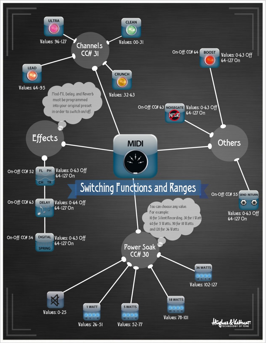
In essence any pot acting as a switch or selector will divide this into regular blocks just as you did yourself. Any channel set up as an on/off switch will use 0-127 and 128-255. Any pot which is a 4-way switch such as the Fx selection will use 0-63, 64-127, 128-191 and 192-255. Any value passed within those ranges will get the selection as you want. Continuous values will use the full range of 0-255. Your modulation speed has a restricted 64 steps so will be set up in blocks of 4. That's 0-3, 4-7, 8-11, 12-15 ... 248-251, 252-255. I do recall something about there being one rogue channel which carried two values in uneven blocks but this is going back a few years now. We should be able to sort it out without too much trouble if you find I am right.
The message 4, Delay Time, makes no sense to me! The GM40 manual says "Delay Time, 128 steps, 51 ms to 1360 ms" but the GM36 says "Delay Time, 128 steps, 51 ms to 1360 ms" and the FSM432 say "Delay Time, 10 ms-steps (double steps), 5 ms to 1360 ms". I think we might assume that the setup has change a little with the GM40, or there may even be a typo, it isn't unknown in those manuals. And I can't see how either of those ranges splits out into a logical pattern for an 8bit setup.

I wonder if there is some sort of issue with real world times being at the mercy of the amp's digital clock time so the values don't come out as straight matches to their digital counterpart? Answers on a postcard...
None of that takes you forward very far I'm afraid but I think it at least confirms your view of how the setup works.


 Setup example.zip